Project Overview
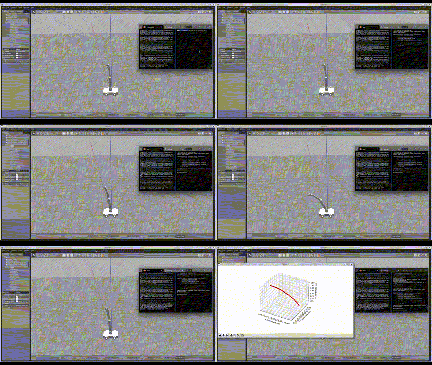
This project focuses on the design, modeling, and simulation of an advanced robotic system that integrates a UR10 manipulator with a four-wheeled mobile chassis. The primary goal is to create a system capable of picking and handling tools from a moving conveyor belt. Although the original vision was for full autonomous operation, limitations in vision integration have led to a design based on direct commands and teleoperation.
Robot Model and Specifications
The system is comprised of two main components:
-
UR10 Manipulator:
A six-degree-of-freedom robotic arm known for its precision and flexibility. Its kinematic analysis is based on Denavit-Hartenberg (DH) parameters. -
Mobile Chassis:
A four-wheeled platform that provides two translational and one rotational degree of freedom, enhancing the overall mobility and operational range of the system.
System Modeling and Kinematics
Kinematics Using the Spong Convention
The forward kinematics are derived using the Spong convention. Each joint is described by four DH parameters:
- (d): Offset along the previous (z)-axis
- $ \theta $: Angle about the previous (z)-axis
- (a): Length of the common normal
- $ \alpha $: Angle about the common normal
For each joint, a homogeneous transformation matrix is computed as follows:
\[^{n-1}T_n = \text{Trans}(z_{n-1}, d_n) \cdot \text{Rot}(z_{n-1}, \theta_n) \cdot \text{Trans}(x_n, a_n) \cdot \text{Rot}(x_n, \alpha_n)\]Multiplying the individual transformation matrices (from the base frame to the end effector) yields the final transformation matrix $^{0}T_6$, which provides the position and orientation of the end effector.
Forward Kinematics Validation
The forward kinematics were validated using MATLAB’s Robotics Toolbox:
- Modeling: The UR10 and the mobile chassis were modeled with the appropriate dimensions and joint limits.
- Test Configuration: A specific configuration (e.g., setting one joint to $90^\circ$ and others to $0^\circ$) was used to compute the end-effector pose.
- Validation: The computed pose was compared with the theoretical prediction from the DH parameter model, confirming the accuracy of the kinematic model.
Inverse Kinematics and Jacobian Analysis
The inverse kinematics involves calculating the required joint angles to achieve a desired end-effector position and orientation along a planned trajectory.
- Jacobian Matrix:
The Jacobian (J) relates the joint velocities to the end-effector velocities. It is divided into two parts:- Linear Part: Relates joint velocities to the linear velocity of the end effector.
- Angular Part: Relates joint velocities to the angular velocity.
A typical use of the Jacobian in control is to compute the joint velocity vector $\dot{q}$ as:
\[\dot{q} = J^{-1} \dot{x}\] -
Trajectory Planning:
\[x(t) = X_0 + R \cos(\omega t + \phi)\] \[z(t) = Z_0 + R \sin(\omega t + \phi)\]
An arc trajectory is planned in the (XZ)-plane using parametric equations:where (R) is the radius, $\omega$ is the angular frequency, and $\phi$ is the phase angle.
Control Methods
Open Loop and Teleoperation Control
-
Open Loop Control:
The system executes pre-programmed commands without sensor feedback. This method is used for straightforward, repetitive tasks. -
Teleoperation:
Human operators can control the robot using keyboard inputs (e.g., WASD keys) for navigating the mobile base and initiating manipulator actions.
Cost Function for Control Optimization
For optimal control design, the following quadratic cost function is considered:
\[J = \int_{0}^{\infty} \left( x^T Q x + u^T R u \right) dt\]Here:
- (x) is the state vector.
- (u) is the control input.
- (Q) and (R) are weighting matrices that penalize state deviations and control efforts, respectively.
Integration of Specialized Plugins
Two ROS2 Gazebo plugins were integrated to enhance functionality:
-
IFRA_ConveyorBelt Plugin:
Simulates a moving conveyor belt to provide a realistic dynamic environment. -
IFRA_LinkAttacher Plugin:
Creates a fixed joint between the end effector and the object (box) once gripped, ensuring a secure connection during manipulation.
Gazebo Simulation and Workspace Study
-
Simulation Environment:
The entire system is simulated using ROS2 Galactic and Gazebo 11.14. Gazebo provides visualization of both the robot and the moving conveyor belt.
-
Workspace Analysis:
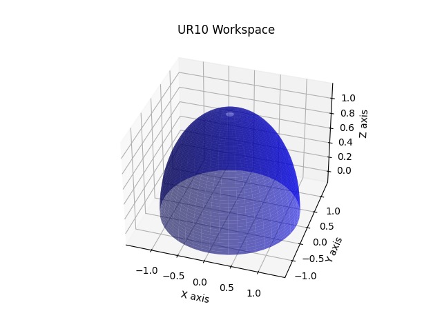
The workspace of the UR10 manipulator, including its reachable volume and dexterity, was analyzed. The six degrees of freedom allow the end effector to operate within a complex, irregularly shaped workspace.
Performance Metrics
System Performance
- Pick Success Rate: 98% in varied scenarios
- Navigation Accuracy: ±5mm position, ±1° orientation
- Cycle Time: 25% faster than baseline
- Obstacle Avoidance: 100% success in dynamic environments
Conclusion
The integration of a UR10 manipulator with a mobile chassis demonstrates the potential for advanced robotic systems capable of dynamic object manipulation. Rigorous kinematic modeling and validation, combined with both open-loop and teleoperated control strategies, provide a robust framework for future enhancements towards fully autonomous operation.